8th & 9th of February 2004
Hole for exhaust system, aligning it all and having finishing rear mounting bracket.
|
|
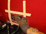
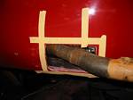
1. Started making cutout for exhaust header. The tape shows my initial guess where it would come out. No measurements were taken, I just did it by eye. A little off, yes, but not too far off.
|
|
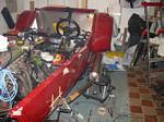
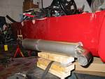
2. Laid all the pieces in place so I could see where the silencer can would be so I could spot weld the mid-pipe between header and silencer.
|
|
3. All in place, spot-welded.
|
|
4. Another picture.
|
|
5. Getting closer now, have amended my guess and have made the rough cut. A near rectangular outlet will look the best I think, with rounded corners. The header will be wrapped also and I'll put some nice plastic trim around the opening once I have finalised its position.
|
|
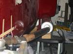
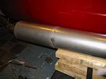
6. Silencer can in place. It's not as big as it looks.
|
|
7. Silencer can is actually two silencers put end to end and then just welded together.
|
|
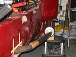
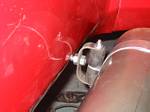
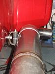
8. Mount for silencer. Not beautiful, but it will do the job of keeping it in place and allowing for some expansion of the tubing as it heats up. Otherwise I risk mounts cracking and all the welds in the header take a lot of the strain and I risk cracks there too. This mount will alleviate a lot of that.
|
|
9. Another view. Also, whole exhaust system has now been professionally TIG-welded together.
|
|