6th and 7th of August 2003
Making mounts for master cylinders and getting bushings in, as well as having a look at the oil sump from Yukspeed.
|
|
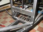
Removed the Westfield mounted plates for clutch and brake master cylinders.
|
|
Another angle, all cleaned up and ready for new plates.
|
|
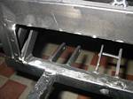
Here are new plates mounted. Welds look pretty crappy, but that's because I only have one of those "cheap" MIGs without Argon gas. I was careful to make sure that the welds melted the surrounding metal so a good bond is formed. It looks crap, but I think it'll work.
|
|
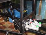
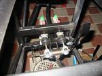
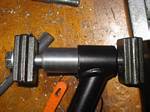
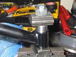
Mounted the Master cylinders also. Looks nice and neat.
|
|
Here's a view from behind. I have to cut down the master cylinder rods so the pedal comes more vertically to match the angle of the accelerator pedal. I'll do that later.
|
|
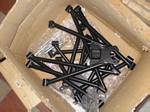
Started on mounting the bushings. All that powdercoating has to be sanded away.
|
|
Halfway on this one. After this, only 23 left...
|
|
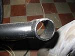
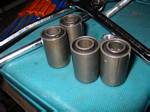
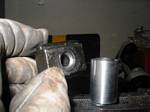
Here's what the bushings look like. No way will they fit inside their holes, they're just too big so they also need to be sanded down.
|
|
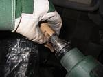
Made an adapter for my drill so I could spin them with it.
|
|
Sand away. Watch the heat, you don't want to burn the rubber inside, or your hand!
|
|
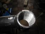
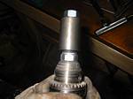
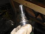
A nice sanded bushing.
|
|
Had also to make my own tool since the middle section of the bushing is slightly larger than the rest. It is 15mm in diameter, so I drilled this hole slightly larger at 15.5mm in a thick piece of metal I had lying around (I actually made two of them, one for each end of the bushing as when it's almost in, it will stick out on the other side, so two are needed).
|
|
Another angle, see how the middle of the bushing sticks out?
|
|
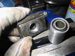
Here's the first step of getting them in. Now it's just wrench time.
|
|
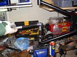
As the threads run out on my bolt, I had three in different lengths of bolt to get the whole bushing in. Use plenty of lubrication (I used WD-40). And yes, I like my workspace all cluttered up, at least all my tools are within reaching distance...
|
|
Even had to use a spacer for one of the bolts as its reach wasn't enough.
|
|
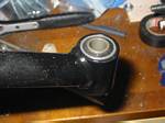
Here it is, the bushing in place.
|
|
I couldn't get all the bushings in completely with my home-made press-system made of M10 bolts - To do all 19 bushings in the control arms, I used 8 bolts and probably as many nuts as they wore out or broke - that's how tough they are to get in. So I did as much as I could then put them in a box and went to where I work where we have a 20ton hydraulic press and did the last part. Problem is, that's not going to work to do the diff mounts..hmm...I did find a solution though, see the next pic.
|
|
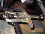
For the diff bushings, I found this nifty tool at work. It will press up to 20tons of force if needed. On the control arms, I had noted a maximum of about 4tons to get the bushings in, piece of cake right? Except that was hydraulic power, this was arm power and it was a real fight but I got them all in in the end...phew.
|
|
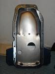
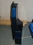
Here are some pics of the Yukspeed oil sump for my Vauxhall/Opel engine.
|
|
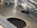
It's shallow at the front and deeper at the rear.
|
|
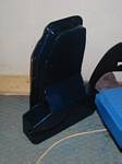
Another angle from below.
|
|
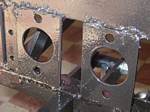
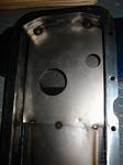
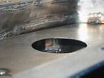
Here's the horisontal baffle. A small slit at the sides of the deep portion, a big hole in the middle for the pickup (my guess) and a hole on the side for the dipstick.
|
|
Here's the slit again.
|
|
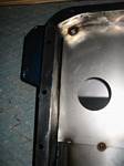
A view through the big hole - you can just make out the far "wall" and its weld.
|
|
Another view on the other rear wall of the sump "wing".
|
|
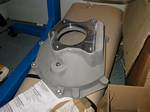
Lovely piece that - the alloy bellhousing to connect between angine and transmission.
|
|
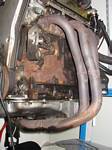
Actually the stock exhaust on this engine isn't too bad, it's a 4-2-1 design that supposedly gives a little more mid-range torque rather than a 4-1 type exhaust which usually puts the torque peak a little higher in the rev band.
|